*Jun 21, 2021 Added few schematics and descriptions.
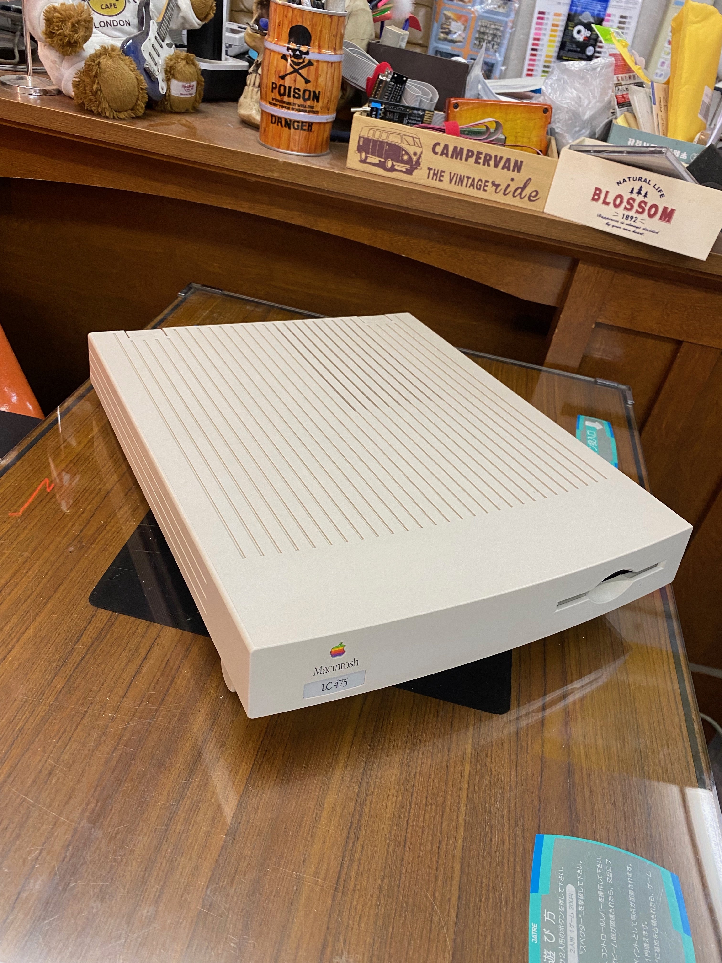
I recently repaired my friend's Apple II Platinum. I didn't want to get any money from him, so I decided to get the LC475 lying in his room for the repair.
However, it had a broken catch lock of the lid and both the power supply and the logic board were out of order.
I used to have an LC475, but it was more than 20 years ago when I was single… At that time, I didn't have a convenient device like I do now. The most convenient ones were ZIP, MO and JAZZ…


Tear down
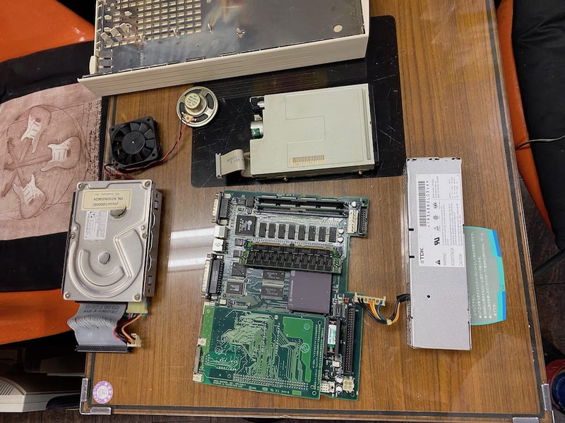
Disassemble everything once as usual. For the logic board, replace all electrolytic capacitors, replace all capacitors with a power supply of 16V or less, and clean and grease the floppy disk. I tried to disassemble the hard disk, but this is a type without a rubber damper and I will give up if it is not in good condition. The case was bleached with RetrObright and it's pretty clean!


Assembly
Assembling is easy, but the plastic case is fragile and hydrolyzed. Models such as LC575, LC630, and LC475 are made of bad plastic and are fragile over time. When actually assembling, there was work to glue and reinforce the broken plastic like a puzzle.
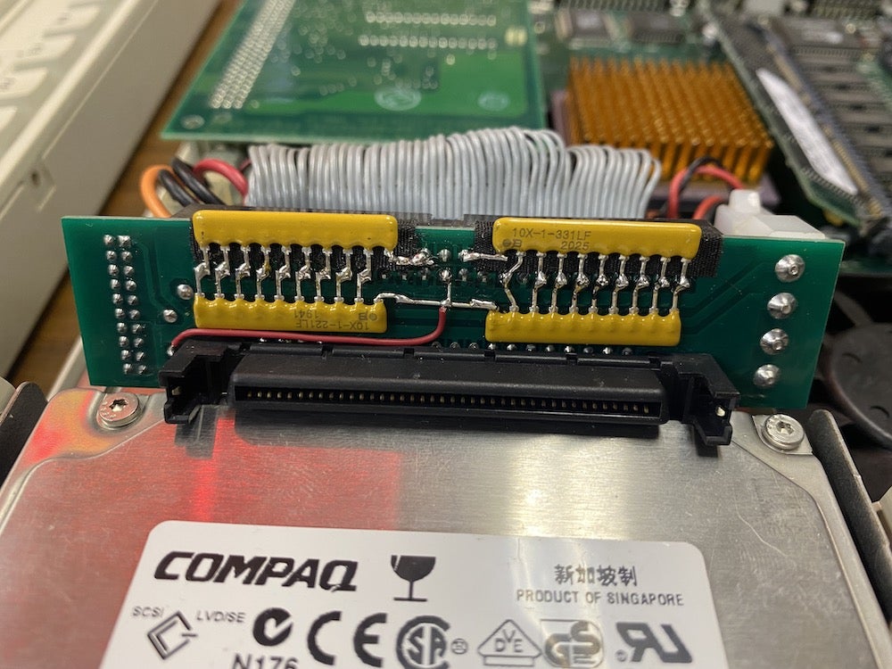
The HDD used Compaq (Seagate) Ultra3 SCSI 18GB to mount four 2GB partitions. This uses 80-pin to 50-pin adapter with homemade terminations.
The following parts have been upgraded.
・Replace the CPU from 680LC40RC25B to 68040RC33A. The lot number is a highly resistant individual famous for L88M. I bought it before and saved it without using it. I would like to overclock and leave the results.

・16MB (80Ns) of RAM was originally installed, but I will replace it with EDO RAM 64MB of 60NS. For overclocking, 70Ns or more is preferable. The logic board also has 4MB of RAM that is directly soldered. In my experience, this can be 80Ns or 70Ns, both of which seem to be OK, in this case.


*It's a very unique design, with a regulator mounted on the RAM board, dropping from 5V to 3.3V to power the chip.
・Two VRAMs are very imprtant point to overclocking. This is a modified genuine VRAM to 70Ns. I rarely see 70Ns in VRAM on the market now. So remove the chip from the RAM card and replace it. Genuine VRAM chips are Mitsubishi M5M482128AJ, new chips are Micron Technology MT42C8128DJ-7. The datasheet shows that both pins are compatible. I really want to install two 512KB VRAMs, but I couldn't get them this time so I have two 256KB. Since VRAM has a Bass clock magnification of 1/3, the upper limit of 80Ns is 37MHz, and 70Ns is 43MHz.

In Pic above, I replaced chips to one board, but this needs to be installed in pairs.
PSU problem
It started up without any problems and I was working on the installation, but after about 20 minutes the HD spin was stopped. I thought the HD was broken, but the main unit does not start even if I remove the HD. The fan is running, but 12V outputs only 10V and 5V outputs only about 3.5V.
I made PSU used ATX for the Apple IIe before, so I started the test using this. This works fine. The 300W power supply has a very good response for the LC475.
I was wondering what to do with the power supply here. The original LC power supply is 50W. The information on some website says 120W, but this is incorrect information. The PSU case has -5V, 12V, 5V amperage output, but the total is 28.485W. This time I will use 12.73W for HD alone, so it seems that the capacity is completely insufficient.
I decided to raise this to at least 80W.

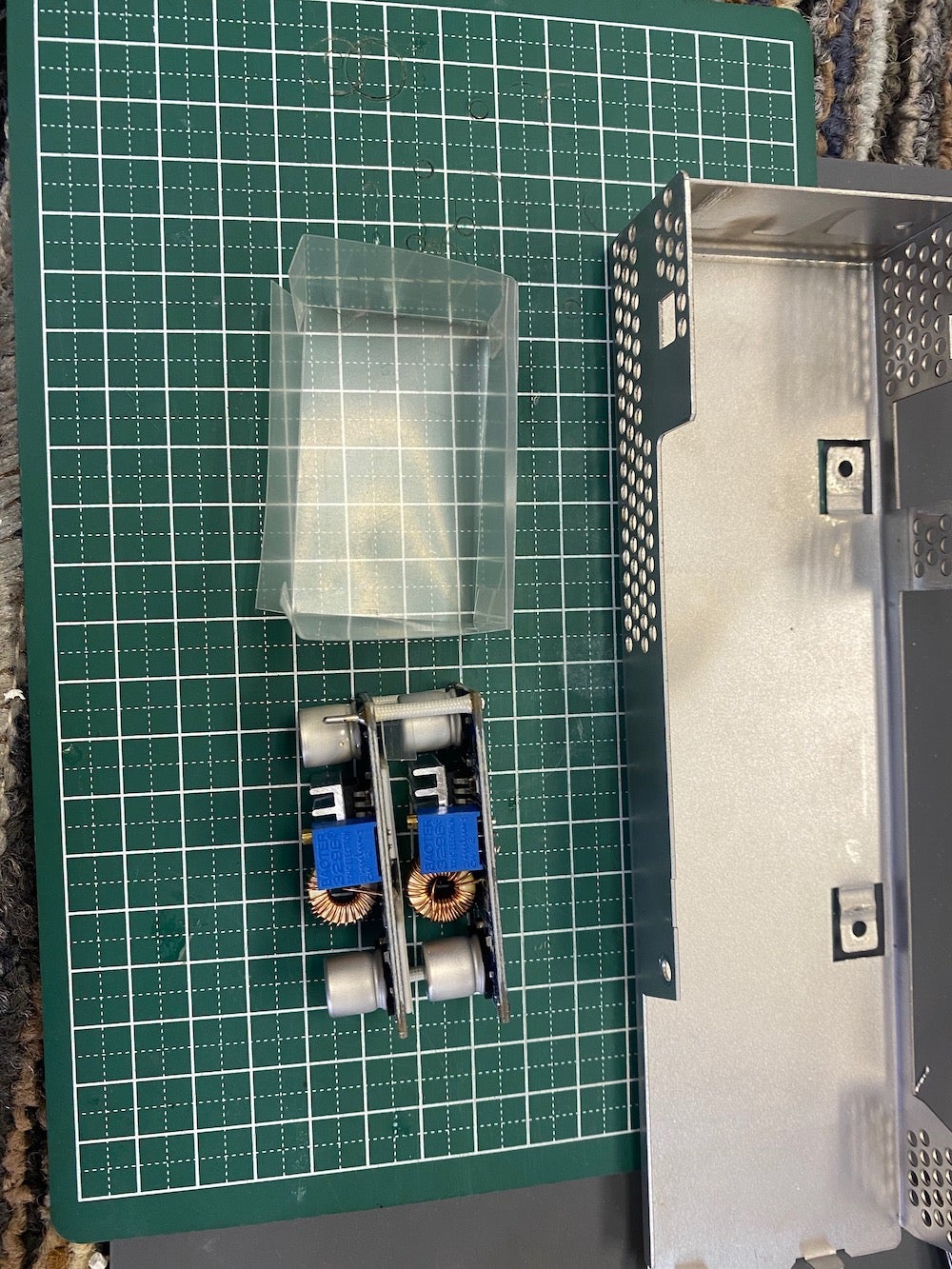
I made some plans, but DELL and HP sold large-capacity DC power adapter for the laptops, so I chose some that fit in the LC.
At the same time, I bought several large capacity DC-DC converters (up to 4A) and negative voltage inverting converters (up to 0.4A).
In terms of size, DELL's 20V / 4.5A PSU (90W) was just the right size. Even if the conversion efficiency when converting is 80%, it is 72W, so this is enough for LC475.
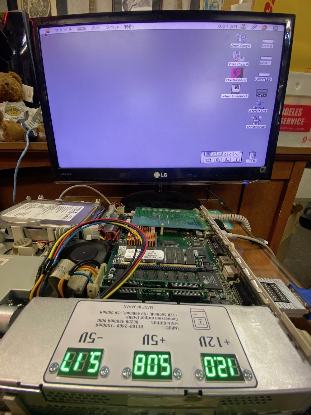
Since the DC-DC converter is variable, I attached an LED voltmeter to the case surface. The rest is firmly insulated and completed. I'm worried about exhaust heat, but I thought it was OK because it was a switching power supply that was originally sealed in a plastic case. No fan is installed. Even with this, the clearance between the case and the contents is very close.


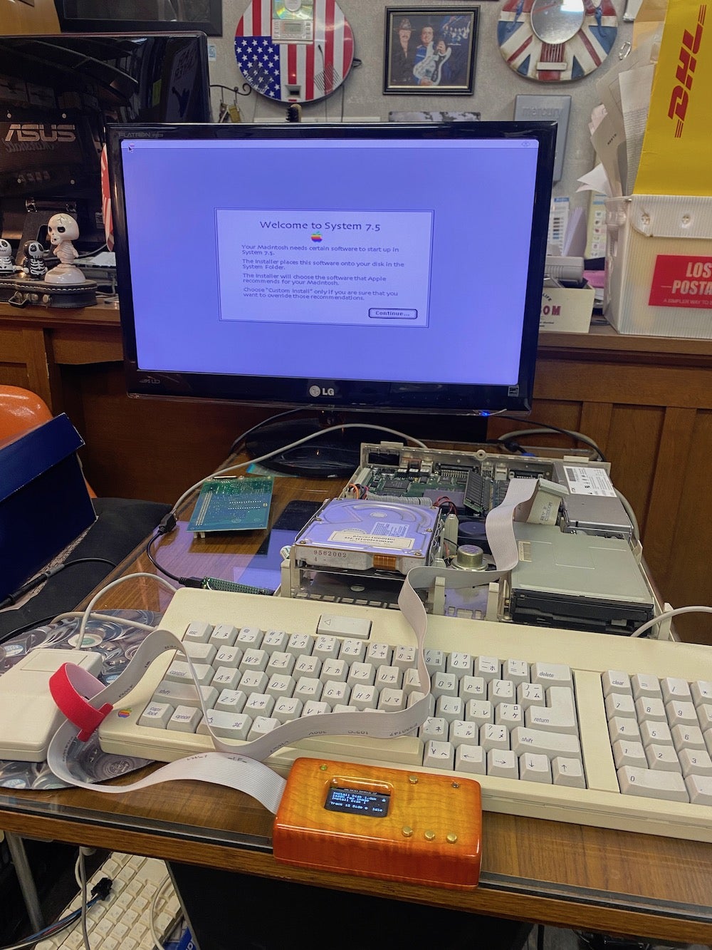
Bootup
The LC475 has been reborn and started up quickly in one go. I felt the operation was fast because the PSU was stable. I installed 7.5.5 and 8.1 as the OS. It works really well.
I’ve been waiting for the Molex 7pin connector to the logic board from Digikey, for the time being, the original connector is installed in a temporary state😫
Over Clocking
The LC475 overclocking procedure is summarized below:
* The rest of the text is the work I did in chronological order.
☆☆☆
Here are 3 steps for overclocking:
☆1. Up to 33MHz:
Two resistance swaps. 301 register R25 to R22, 472 register R21 to R24.
This overclocking method changes the source transmission frequency of the programmable clock generator 343S1135 located in U17.

*More details can be found on the website below:
☆☆2. Up to around 37MHz:
In addition to the method ☆1 above, install a crystal oscillator 20MHz(CPU clock is 20MHz x 2 =40MHz). + 5V VCC and GND are soldered to genuine oscillator pins. *Genuine crystal oscillator doesn't remove this and leave it as it is.
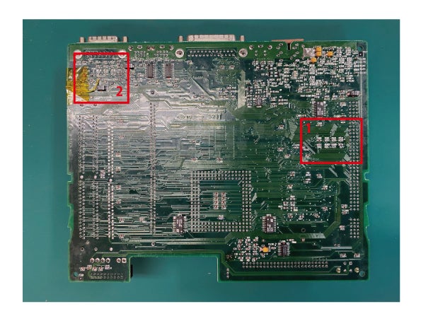
For the Oscillator output, remove the R93 resistor on the back of the PCB and solder it to the pattern toward the center of the board.
This means that the output from the original crystal oscillator is blocked from the input to pin 8 of the MC88920, which is a clock driver, and the output of the newly added crystal oscillator is interrupted.
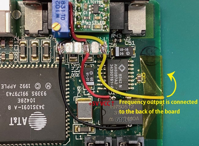

Notes: The above image uses the adjustable oscillator I made, but the pinout when connecting an ordinary crystal oscillator is as shown in the image below.At this time, select and use a crystal oscillator that is driven by +5V.

*A heat sink and sometimes a cooling fan are required because it generates a lot of heat.
☆☆☆3. Up to 40MHz over:
In addition to the ☆1 and ☆☆2 methods, replace the clock driver "MC88920". The available driver can be replaced with MC88916DW70, MC88916DW80, MC88915DW55 etc... In addition, replace VRAM with high speed 70Ns. It's hard to get it now, so it's best to get only pin-compatible chips and replace them. Replace low-speed memory with high-speed 70Ns or more(*If you feel it is necessary)
*Since the serial port cannot be used normally after about 42MHz, 41.8MHz or less is preferable to use it without problems.

https://ameblo.jp/keroxiee1016/entry-12614308377.html
About VRAM. This is my past blog, but please refer to the above as well. * The method for attaching the crystal oscillator is different.
*I will upload the schematic later.
☆☆☆
Overclocking is a way to get the crystal oscillator to interrupt the clock driver, just like the LC575 and other models. The clock driver has more work than just driving the CPU clock, so it cannot be replaced.
The corresponding frequency of MC88920, which is a clock driver, is originally 12.5MHz (CPU magnification is doubled to 25MHz). So, if you put in a larger frequency, there is a limit. The famous magazine "Dooping Mac" had such a description. "Even if you install a 40MHz oscillator, most of them are only about 37MHz. In rare cases, there are some individuals that output 40Mhz, but only a few…”
At first... I tested it just only move resisters (see the above ⭐️). When overclocking from 25 to 33MHz, just swap the two resistors and we don't need to add the crystal oscillator.
This is the result, works no issue and the LC475 looks well like a genuine from the OS.

It's almost same score with the LC630 (Quadra630).
Then ... this time (see the above ⭐️⭐️) I tried to overclocking to 40MHz with a 20Mhz crystal oscillator, but my LC475 was limited to 37.84MHz🤷♂️

I used this Epson 20.00MHz crystal oscillator for this test.

From here, I was waiting for clock driver from Germany and working on other projects for a while. During that time, I was looking for a crystal oscillator, but I wondered if I could make it variable. This time, I made an adjustable oscillator module with a small oscillator of SOT23 called LTC1799. I installed a 1K Ohm resistor and a 1K Ohm trimmer, wired it.(*Although it is a 500 Ohm trimmer pot on the wiring diagram, it is preferable considering the variable range.)
In my calculation, this variable range is calculated to be 37.7MHz to 46MHz. I have a module, but I don't know if it will work. I don't think anyone has done it at least on a 68K Mac. I will leave this for the time being and try it at the end.
If you don't have the module, you can build it your own because the circuit is very simple.
In the figure below, I was planning to install a variable resistor of 500Ω, but I wanted a down margin, so I set it to 1KΩ.
Editted on February 1, 2022: Currently, this idea has been reproduced with a product called Spicy O'Clock. If you are interested, please see here.
Two weeks have passed since then, and the clock driver arrived from Germany, so I immediately replaced it. The clock driver to be replaced is MC88916DW80. To make the PCB easier to work with, remove the surrounding parts as much as possible and replace them with a solder hotgun. Be especially careful with SCSI 50-PIN connector as this is easy to melt. I'm used to this work, so I did it cleanly.

However, it never turned on and booted....Damn it! This is a failure. Probably a bad chip. My shopping is often unsuccessful. And this time I decided to remove the MC88916DW70 from the logic board of the LC575(*which had an brocken graphics chip) and install it.
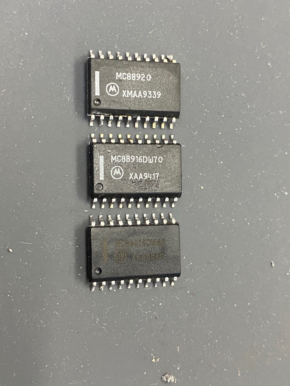
From above: MC88920 / LC475, MC88916DW70 LC575, MC88916DW80 / difected driver chip from Germany.
When it was completed, I checked it all, and when I turned on the power, a pleasant boot chime sounded!!! It went well!!! This time, 40MHz is properly output. Perfect!

Now that the clock driver has room, we will push the limits. Install the LTC1799 module I made earlier. Idk if this will work. Calculate the frequency and set an arbitrary DC resistance value in advance with a tester. The first thing I tried was a resistance of 1.5K Ohm, which should be calculated to be 20.8Mhz and the CPU clock should be 41.6Mhz.
Perfectly calculated!

Measure the DC resistance and set the clock.

When I turn on the power switch, it will start without any problem! Great success! If I check the clock, I can see 41.6Mhz, which is the theoretical value. I gradually increased it from here, but the conclusion was that it did not reach 43MHz. If it is set to 42.7MHz or higher, it will stop during startup. The clock comparison is as follows.


After work
I finished with overclocking at the end, but this LC475 is a low-end but pretty interesting Mac. Even if we don't use an accelerator, we can get almost twice as fast with just an idea. I think it's not so hard.
I also explained that overclocking above arround a 38MHz doesn't work on this machine because of the characteristics of the MC88920, but even if the VRAM is 80Ns it won't work. The screen becomes full of dust at 40MHz and above. I said that it is better to have faster RAM, but in reality, the speed of VRAM is the key.
I wanna 12" RGB Monitor to stack on this beautiful LC475...
I used to have a PPC601 card in the same LC475, but it wasn't very attractive. I would like to have the IIe card installed on my PDS, even if I get it again. Thx for for reading it until the very end, I'm very happy now. Have a nice Mac mods!