International Research Journal of Engineering and Technology (IRJET) e-ISSN:2395-0056

Volume: 09 Issue: 10 | Oct 2022 www.irjet.net p-ISSN:2395-0072

International Research Journal of Engineering and Technology (IRJET) e-ISSN:2395-0056
Volume: 09 Issue: 10 | Oct 2022 www.irjet.net p-ISSN:2395-0072
Sri
1,2 Student B.E Mechanical Engineering, Sathyabama Institute of Science and Technology, Tamilnadu, India 3 Assistant Professor , Dept. of Aeronautical Engineering , Sathyabama Institute of Science and Technology, Tamilnadu, India. ***
Abstract - This article presents a review of acoustic characteristics of chevrons in modern bypass Jet engine. Jet noise is still a major concern for civilians and to the environment. Manufactures and research engineers are actively working to provide a viable solution for noise reduction without trade-off fuel efficiency. One such passive method to reduce jet noise is by using either chevrons at the end of nozzle. This review paper discusses various geometries in chevrons and nozzle along with their computational analysis on acoustics. This gives a wider perspective to understand these passive methods and helps researchers to come up with novel solution addresses the earlierimplications.
Key Words: Chevron nozzle, Jet Engine, Aeroacoustics, Bypass,Noisereduction,CFDAnalysis,Notched,RANS,Jet Noise,Chevrons
Abbreviations:
BPR: Bypass Ratio , SFN: Separate Flow Nozzle , SPL: Sound Pressure Level, EPNL: Effective Perceived Noise Level, OASPL: Overall Sound Pressure Level, NPR: Nozzle Pressure Level, API: Acoustic Power Index, TKE: Turbulence Kinetic Energy, ANOVA: Analysis of Variance, MDOE: Modern Design of Experiments ,DNS: Direct NumericalSimulation
Nomenclature: Z:MachNumber, Deq:EquivalentDiameter, Mij:LocalMachNumber, Vj,mean :MeanJetVelocity, St:StrouhalNumber, Dcore :CoreDiameter
Jet engine is a reaction engine, basically every action has equalandoppositereaction.EarlyJetenginehastosucka large volume of air into the combustion chamber .Along with fuel-air mixture it becomes a controlled explosion which increases temperature. As a result volume of air intake is increased. This is directed outward through nozzle[1-9] Thesejetplumesreactwithambientairinthe atmosphere. When two different air masses at different flow speed of different temperature causes turbulence or vertices .These vortices generates noise .The difference in flowspeedbetweenengineexhaustandambientairisvery large ,So there is huge noise[10-11] .This became a concern for civilians and natural habitats due to its unpleasant screening noise, especially during night. So in late 1960’s airplane manufacturers came up with commercial bypass jet engine[12],[14],[52]. In modern jet engines,thereisahugefaninfrontofengine.Thisfanuses the energy created by jet exhaust and converts it into kinetic energy. This huge fan operates at relatively less speed than the exhaust. Due to this the bypass air coming from bypass ducts provided mixes up with ambient air. These plumes are uncontrolled but has less noise than earlier jet engine without bypass. These bypass air and ambientairMixingencapsulatesallaroundthejetexhaust and it reduces the intensity of vortex. This bypass ratio engineshadreducedaroundnearly30%-40%fromearlier jet engines without bypass .Still with bypass jets had substantial noise. Later , NASA came up with Chevrons Many research lab testing and full scale flight tests conductedaspartofQuiettechnologyDemonstrator(QTD) programme have proven that using chevrons to bypass turbojet engines is effective way of passive method to reduceinbothsubsonicandsupersonicflows.[16]
Three main sources of jet noise are due to aerodynamics, engineandothercontrolsystems.Primarilynoisefromthe engine is because of jet plumes getting away of exhaust nozzle[1].Whenhighspeedjetwithdrawfrom theengine
International Research Journal of Engineering and Technology (IRJET) e-ISSN:2395-0056
Volume: 09 Issue: 10 | Oct 2022 www.irjet.net p-ISSN:2395-0072
has intrinsic shear layer and it swirls up into vortices like ring-shaped .This disintegrates into turbulent plumes mixing with ambient fluid which results as a source of noise[2]Jet noise has been considerably decreased by increasesinBypassratiointurbofanenginesThisreduced the velocity gradient[3]Some of passive methods to reduce noise in jet engine are chevrons, notched nozzle, micro tabs, corrugated nozzle, inverted velocity profile[48] Active methods to reduce noise are water injection, air injection, nitrogen injection. By these methodsmoreornearly2-3dBnoisehasbeenreduced.[4]
Incommon,mostlynoisearisesduetopressurevariations in an unsteady flow. Pressure variations occur in an unstable flow to counterbalance momentum variations. “These pressure changes are transmitted to the surroundingfluidandspreadoutwardfromtheflowsince allrealfluidsarecompressible”[5].Thesoundthatisheard is made up of these pressure waves in the surrounding fluid.[5]
When a jet fluid strikes a background fluid that is stationary or flowing relatively slow, shear among in motion and immobile fluids creates a fluid mechanical transcience that makes the interface to disintegrates into vortices. Then these vortices move subsequent by speed thatisbetweenthehighandlowspeedflowsinmagnitude. It follows the indicated velocity is subsonic or supersonic in compared to exterior flow determines the characteristicsofjetnoise[6]Thehighspeedexhaustgases are responsible for most of noise, particularly during takingoffandlanding.[7]
ByLighthillseighthpowerlaw[8], Soundpower jetarea×(jetvelocity)^2 (1)
Chevrons are jagged back edges at tip of nozzle. The triangular shaped cut outs at edge of nozzle reduces jet plumeslengthbyindicatingstreamwisevorticesintoshear layer which enhances the mixture. This results in reduced jet noise. Chevrons transform an axisymmetric jet into lobbedjetatcloseproximitytonozzle,intensifyingmixing owing to expanded shear layer perimeter. Subsequently themidlinevelocitydecayratearises,thetheoreticalcore length shrinks and the spherical cross sectional of jet changestodisclikeshapeboundedof asmalllengthof5D.
The aforementioned effects are amplified by increasing chevron penetration, especially when it occurs in mixing layer’s thinner zone. “Chevrons shift the acoustic energy
from low frequency to high frequency, which directs beams to greater polar angles where OASPL is improved”[24]. Chevrons emit noise from near field move efficiently toward polar angles greater than or equal to 50°[24].ChevronsenhancethehighfrequencySPLatpolar angles greater than 40° and decrease the low frequency SPL at all polar angles in distant field. But the corresponding frequency spectrum multiply in SPL at higher frequencies for probe in thin blending layer and at low frequencies for probe on thin blending layer and low frequencies for penetrating thick blending layer, despite the fact that the resultant OASPL for same penetration of chevron petals is above or below invariant irrespective of theirlocation.[24]
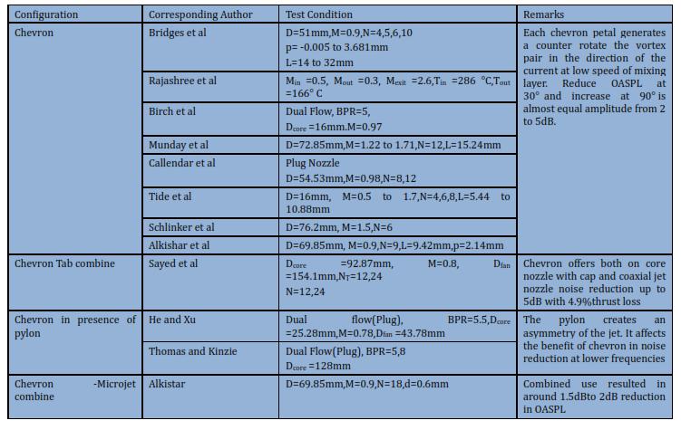
3.1Chevron configuration:
“
Geometry of chevron nozzle is defined by the parameter such as number of chevrons(N), length of chevron(L), tip angle(β)and penetrationangle(α)”[9]
Fig1[9]
Baseofthesinglechevron(b)canbecomputedby[9] b=π×(D/N) (2) tan(β/2)= b/(2L) (3)
Bycombining(2)and(3), (L/D)×(tan(β/2)×N)= π/2 (4)
Nozzle length that is influenced by nozzle exhaust diameter[9]
L’ =4.25×D (5)
Heightofchevronis[5] H=b/2 (6)
These formulae implies that chevron length is reliant on chevroncountandtip angle.Chevron arrangement can be
International Research Journal of Engineering and Technology (IRJET) e-ISSN:2395-0056
Volume: 09 Issue: 10 | Oct 2022 www.irjet.net p-ISSN:2395-0072
shown as “N×βy”. From eqn(4),it is understood that L/D is primarily depend on chevron count and tip angle. This relation provides an insight that these fundamental variables determines the geometry of chevron are interrelated and that it is impossible to change one variable without also affecting the others. Therefore extremely considerable consideration goes into selecting chevron configurations so that the impact of each individualparametercanbedetermined.[9]
Oneeffectivetechniqueforminimisingjetnoiseischevron which improves the mixing of fan ,core and ambient streams more quickly than traditional nozzle without affecting efficiency [9], [10].The triangular cut out placed along thenozzle’s trailing edgecausestreamwisevortices to form in shear layer, increasing mixing and shortening the duration of jet plume. As a result the chevrons effectively boost mixing while lowering overall jet noise. The chevrons increase the noise when there is too much mixing. The benefits of noise reduction are not experienced if it is insufficient. The nozzle reduces less frequency mixing noise from highly turbulent flows by allowing the core and bypass flows to mix[10] With baseline nozzles, the azimuthal component makes up the majority of vorticity in shear layer. Such vorticity gather into distinct ring shaped structures. These structures undergoesdistortionwhilespreadingdownstreamcausing intense turbulence to develop. Contrarily the streamwise vortexare segment of continuous flowand possess a time average phenomenon. The effluent boundary layer is the primary origin of vorticity within the nozzle. Simply said, the chevrons disperse come of it at expense of azimuthal component. This often leads to decrease in turbulent intensities with reduction in noise. Heavy mixing on the other hand will raise levels ,so optimum mixing is to be employed[15].
Thisconceptprovideschevronalignmentwithflowforthe cruising period of jets, which is most important for fuel economy, and allows for fan chevron penetration at takeoff, in which SPL reduction is must important. Shape memory flexures were included into the chevron in variable geometry chevron design. Shape memory alloys have unique phenomenon to change shape at a specific temperature. During take-off the chevron nozzle shape is different, then during cruise they can have aerodynamically effective shape[11][54]. Even though chevrons are said to have only attenuated a jet engine
exhaust noise by roughly 2 to 3dB at low polar angles, its stillaneffectiveOASPLattenuation.[12]
Table1 [13]
Table 2 [13]
International Research Journal of Engineering and Technology (IRJET) e-ISSN:2395-0056
Volume: 09 Issue: 10 | Oct 2022 www.irjet.net p-ISSN:2395-0072
a)Chevrons in core nozzle: The difference in EPNL is because 3I12B SFN penetration the boundary layer and 3C12SFNremainsinlinewithcorestreamline. b)Chevrons in fan nozzle: 3BC24 SFN was 0.2EPNL dB louderthan3BB
c)”Core Chevrons with Fan Chevrons simultaneously”[13]: With 3I12C24 configuration reduction of 2.7EPNl dB is seen at Z=1.07 and remains uniform beyond high thrusts. Simultaneously adding of chevrons in core and fan resulted in additional reduction of 0.6EPNdB compared to 3I12B. 3I12C24 results in overall reduction of 2.7dB compared to 3BB SFN. At low frequencies, the resulted noise reduction are promising butathigherfrequenciesthereisanexcessnoisewhichis undesirable .When used as fan nozzle instead of core nozzlebothchevronswerefoundineffective.[13]
James Bridges et al 2004, studied ten models of chevrons with varied chevron counts, penetrated length and chevron symmetricity to find relationship between chevron geometric flow characteristic and far field noise. The hot condition and cold condition have been tested at Machnumber0.9.Thestudyimpliedthatchevron’slength was not influencing either flow or sound. In particular for low chevron counts, chevron penetration raises high frequency noise and decreases lower frequency. Number of chevrons is a significant factor with excellent lower frequencies reduction that is accomplished with more chevron count without severe higher frequency penalty while the asymmetry of the chevrons affected. The study alsodemonstratedthateventhoughthehotjetdistinguish structurallyfromcoldjet, overallchevronparameterwere same. The most important factor in noise creation in chevronsisvelocitygradient[14],[15]
Table 3 [14]
InSMC001andSMC006,thefrequencydecreaseat150°is same as high frequency rise at 90°, which is 3-5dB above circular jet(SMC000). SMC005 was insignificantly distinguishablefromroundjet(SMC000).Thenoiseofcold jet increases more at broadside angle and decreasesmore atrearanglethanhotjets.
Callendar et al conducted experimental studies on impact ofchevron-nozzleonnear-fieldaeroacousticsforaisolated flowing exhaust system. Penetrating level of chevron was varied to understand the impactsofcertainparameters in near-field aeroacoustics. Two chevron nozzles with eight chevron lobes were studied to understand the level of penetration. One nozzle penetration level was modest. Based on magnitude of boundary layer thickness, other nozzle has around two times compared to nominal level[16] It was found that nozzle penetration was more significantthanchevronlobecountfornearfieldreduction innoise.[[7],[16] Table 4 Nozzle
Summary [16]
International Research Journal of Engineering and Technology (IRJET) e-ISSN:2395-0056
Volume: 09 Issue: 10 | Oct 2022 www.irjet.net p-ISSN:2395-0072
Ps tide et al, investigated the novel possibility of using sinusoidalchevronprofileandalsotheeffectofasymmetry inchevrons[7]
SPL=10log10(Prms/ ) (8)
OASPL=10log10 ∑ (9)
The NPRused for the experiments ranged from 1.5 to 5.0. “Analysis was done on acoustic properties such as OASPL, spectrum, directiveness, acoustics power and broad band noise”[7]. The findings show that noise reduction is significantly influenced by both chevron asymmetry and chevron lobe profile. For both of the tested symmetric chevron nozzles(Chev6-0 and Chev6-sine), the OASPL is reduced by about 2.5dB. “Due to the impact of smooth chevron lobe shape, the sinusoidal chevron nozzle(Chev6sine) exhibits improved noise reduction for all emission angles at higher levels of NPR”[7]. Due to the lower dispersionofvorticityinsidetheaxialvortex,theshockcell lengthisalsoshortestforChev-6nozzle.
Table 5 Geometric details of Nozzles[7],[18]
For Chev6-Asym asymmetric nozzle, a moderate drop in OASPL of 1dB is seen along the larger isosceles triangular side and significant reduce of 4.5dB is seen throughout smallerequilateraltriangularside.[7],[17]
K.Srinivasan et al conductedexperiments with number of chevrons and penetration as parameter at various nozzle pressure ratios. The findings show that for less and mediumnozzlepressureratio,thehighestnoisereduction is produced by a large chevron count with low level penetration.[18]
The6and8lobedchevron nozzleprovidearound2dBand 4dB reductions in noise but the 4-lobed chevron nozzle only decreases noise by 1dB. The chevron nozzle with 8 lobes and 0° tapering offers greatest noise reduction of everyevaluatedgeometries.
At low values of NPR, chevrons with 4 lobed and tapering anglesof5°and10°generategreater noiseincomparison to baseline nozzle. The chevron nozzle sometimes more noisethanthebaselinenozzleathigherpenetrationlevels because the mixing becomes more aggressive as penetration angle increases. The chevron nozzle with deeper penetrated nevertheless exhibit improved noise reduction for all mission angle of larger levels of NPR. It can be concluded that at low pressure ratios, chevron count is the most important criterion for noise reduction whereas at high NPR ,chevron penetration is very important. As number of Chevrons and penetration increasetheshockcelllengthwasobservedtodecrease.It wasalsonoted that regardlessof NPR, theforward angles forentirechevrondesignsarenoisierthantheaftangles.It was found that for all chevron nozzles, acoustic efficiency islessthan1%.8-lobedchevronnozzlewith0°taperhave the lowest acoustic efficiency. Four lobed chevron nozzle has highest API among all tested configurations whereas eightlobedchevronnozzlehasleastAPI[18]
R.H. Schlinler et al conducted experiments to examine OASPL, directivity patterns, far field spectra of baseline roundCDnozzlewith3’’diameternozzleexitdiameterand chevron nozzle with 6 chevron count of 3” diameter with 1° angle of penetration was tested. Under conditions with Mach number = 1.5, Stagnation temperature ratio ranging from Tr= 0.75 to 2 . At frequencies above Strouhal peak, slender penetration chevron were found to have lesser noise level of around 2dB in aft quadrants. At 90° and forward angles wideband noise level increased. The main advantage of chevron geometry was at under expanded operating conditions lowering intensity of screech tone.
International Research Journal of Engineering and Technology (IRJET) e-ISSN:2395-0056
Volume: 09 Issue: 10 | Oct 2022 www.irjet.net p-ISSN:2395-0072
Therefore a less penetration chevron design may helpful instancesrequiringthemoderationofscreechtone.[19]
Strouhalnumber,St
St=(f×.Deq/Vj,mean) (10)
O.Rask2011etalstudiedhowchevronsmodifiesnoisein jets with consequent flight effect. The study reveals that chevron in any case reduces the shock cell spacings, as seen by static pressure tests,which accounted for the rise in frequency for the aeroacoustic results. Near the nozzle exit, the chevrons raised turbulence levels (X/Deq=2) but they had little or no impact on spatial changes in static pressure[20]. In case of Chevron, large peak amplitude of shock-associated noise was caused by high turbulence levels, √ )/(Vexit)= √ Vexit (11) u–axiallyvaryingvelocity visradiallyvaryingvelocity
Theinnershearlayerweakenedwithincreasingsecondary flow,whichinturnreducedmixingnoiseanddownstream level. Regardless of the secondary flow Mach number, the chevronsalwaysloweredthemixingnoise.[20]
Far field observations at aft angles showed that mixing noise was reduced as secondary flow was increased. The inner shear layer had the highest values for secondary flowsatthedownstream(X/Deq=8)accordingtoflowfield results. Separate flow chevron pylon based nozzles are to experimental analysis for purpose of reducing jet noise under take off conditions by Jing Yu. The testing results show that pylon reduces noise at low frequencies. The additionofapylondiminishesthenoise reduction usesof chevron nozzles as compared to chevron nozzle without pylon. The results implies that pylon-chevron combined has less influence on directiveness of Overall Sound PressureLevel .[21]
Kaleeswaran in 2016, conducted experiments to suppress noise level of supersonic jet with chevron nozzle of by varyingNPR.Threeconfigurationofnozzlewaschosenfor experiment, nozzle with 10 chevrons, 14 chevrons and baselinenozzle.
Regressionequationfornoisemeasurement,
Noise(dB)=126+0.600(A)-0.130(B) (12)
WhereA-NPR
ThisequationimpliesthatnoiseleveldropwithlowerNPR and with increase in no. of chevrons. It was found that regardlessofnumberofchevronsused,noiselevelstendto rise as pressure ratio rises. And also when number of chevron increases at nozzle exit the noise level tend to drop.Noiselevelsfor14chevronsdecreasesfrom126.2dB to125.3dBwhentheNPRwasreducedfrom3.5to2.5.Asa result of adding 14 chevrons , 2% reduction in noise level wasobservedwhenNPR3.5[22]
Taguchi and Anova techniques were used in this experimenttodetermineparameters.
MathematicalequationfromS/Nratio
S/N=-10log(1/n 1/Yi 2) (11)
Y-observeddata
n–no.ofobservations
Table 6 Measured values and S/N ratio[22] The configuration that has lowest noise level highest S/N ratio. It is found from this study that nozzle with 14 chevrons and NPR 2.5 has high S/N ratio and it is appreciable noise reduction characteristics. This gives an overallideathatinnoisesuppression,numberofchevrons was dominant factor followed by NPR within 3.5 to 2.5.
International Research Journal of Engineering and Technology (IRJET) e-ISSN:2395-0056
Volume: 09 Issue: 10 | Oct 2022 www.irjet.net p-ISSN:2395-0072
Leopoldo P. Bastos et al conducted experiments to study jetsurfacecontactcoupledwithchevronnozzlecausesfarfield noise. The experiment uses SMC000(without chevron) and SMC006(with chevron) which was initially experimented by Bridges[2],[22] It was found that noise levelsforweaklyintegrateddesignsincreasedwithsurface length and decreased with radial location. The far-field observation was at radial extent of 2.33[22] .On other hand, the acoustic advantages of chevrons were insignificant for highly integrated jet configurations and raised noise levels at medium and at all structural valued[23]
S.R. Nikam et al investigated acoustic parameters of chevron nozzle at M=0.8.Chevrons cause lobe sheared layeracross the notched area , increases jet’ssurfacearea especiallyinshortdistancefromnozzlewhichshortensthe possible core length and improves mixing. As penetration increases closer to nozzle lip this impact becomes more pronounced in thinner mixing layer[24]Nikam suggests a more simpler method for finding peak of centreline velocitydecay rate which is the primary noise source. On compared to simple baseline nozzle , total noise level measured alongside jet edges are greater at near distant downstream of chevrons but decrease at far distant downstream. The tendency is seen to be reversed at high frequencies, even if they continue to subdue the lower frequency noise. Additionally at high frequencies with increasingpenetration forshallowpolarangles asregards jetaxisbutatlargerpolarangles.[24]
Acoustic and hydrodynamic noise are two components thatmadeupnoisethatiscomputedinnear-fieldatthejet edges. When compared to acoustic component the hydrodynamic component is found to be reduced by chevrons.[24],[51]
For a given length and penetration individual chevron petalcreatesa setoftwostreamwisevortex,henceanrise in petal count increase the overall strength of streamwise vortices. On the other hand, too many chevrons petals would reduce the size of chevron which is influenced by boundarylayer’sviscouseffect.Eightchevronspetalswere chosenofthoseCH-3isfoundtobemoreefficientthan12 petalnozzle.Afterthepotentialcorehasended,thedegree of centreline velocity decay increases quickly with axial distance, attaining its peak near the inflection point and then decreases more slowly . The region of extremum strain, which is abducted to be the source of extreme turbulence and the main source of noise it is where the centreline velocity decay rate peaks.[24] CH 1-3 found to be effective in increased centreline velocity and reduced
corelength.Incontrasttochevronnozzles,thebasenozzle exhibits significant noise level starting at X/D= 4 near the jet edges and moving towards the nozzle’s penetration increases[24].
Innearfield,chevronnozzleislouderthanbaselinenozzle due to creation of lobe in jet through notches. Calender et alfoundsuchachangeinpeaknoisezonenearthenozzle’s exit for chevron nozzles with dual steam flow. OASPL grows closer to nozzle outlet as penetration power of streamwise vortices increases with number of chevron petals.Chevrongeometryhaslittleeffect ornearfieldlow frequency noise radiation pattern for dual stream flows.[16]
Table7 [25]
Under different test settings the far field spectra for jets haveshownthat largestnoiseleveloccuredinarestricted region ofStrouhal frequencyfrom roughlySt=0.18 to0.23 which is connected to major noise source along =30° [17],[55]. “Noise from jet flow in far field is dependent on nozzle diameter, jet velocity, distance from nozzle, polar angle, temperature of jet, atmospheric absorption coefficientetc”[24]
OSAPL= OASPLref –10log(Dref/D)2 + 10log(rref/r)2 –10log(uref/u)2 (13) nvaryfrom7to8at =90°and8.5to9.9at =30° It can be noted that polar locations between 90° and 70° have considerably greater noise levels coming from chevron nozzles. The fine scale structures that are developing in mixing are principally responsible for noise
International Research Journal of Engineering and Technology (IRJET) e-ISSN:2395-0056
Volume: 09 Issue: 10 | Oct 2022 www.irjet.net p-ISSN:2395-0072
that radiates to these polar points. From 60° to 40° the difference in noise level becomes negligible as we approach downstream near the jet axis. It’s alluring to observe OASPLsuddenlydropsbyroughly1.5dBfromthe chevron nozzles at =30°, which are closer to jet and where noise from large scale structures growing downstream of potential core makes up majority of noise.[24]
4.7%thrustpenalty.P10B22L40chevron with3.6%thrust penalty offers OASPL reduction of around 3dB. “The numerical findings computed an OASPL benefit to thrust loss ratioof0.82,whereasthelinearmodel anticipated an OASPL benefit to thrust loss ratio of 0.91,sharing that MDOE model is not applicable outside of parameter space ”[25]
Saravanan et al investigated blending properties in subsonic and sonicjets are affected by a chevron with tab fixed at outlet of coflowing principal nozzle. In the experimentjetwithMach equalsto0.6and0.8wereused. For each of these jet Mach number decay was estimated usingthecoflowbaselinenozzle, chevronnozzleandtabchevron nozzle. The potential core length of baseline coflow nozzle has been measured to be X/D=6.8. The possible core length is reduced for nozzles with tabbed chevrons nearly X/D ratio equals to 5.8 and X/D ratio equals to 0.8 respectively with 88.23% decay in core lengthatMachnumber=0.6.
In comparison to chevron nozzle with baseline nozzle it was discovered that the tab-chevron was successful in cuttingthepossiblecorelengtharound88.23%.Theradial profile demonstrated that tab-chevron blending enhancementwasefficientoncomparedtochevron-nozzle blendingenhancement.[58]
Tabel 10[58] M=0.8
Brian et al conducted experimental testing and CFD modelling of shield chevron nozzles, in side flight conditions with several chevrons attachment configurations, a tri streamed inverted velocity profile nozzle simulation has been performed. A jet noise determiningmethodwasusedtopredictfar-fieldnoisefor each resultant flow field. When compared to chevron that don’t alternate ,chevron that alternate into primary stream and tertiary buffer stream exhibit a significant reduction in low frequency noise but has comparatively insignificant high frequency and thrust penalty. A three parametermatrixchevronsofalternatingpenetrationwith variedprimarystreamwascreatedusingMDOEapproach. ByMDOEresult,240chevronreducedOASPLby3dBwith
This
pushes tabbed chevron vortices away from jet axis, generating an off centred peak profile. The tab-chevron nozzle accelerates the spread of jet and promotes greater blendingintransferzoneandshearedlayer.[58].
International Research Journal of Engineering and Technology (IRJET) e-ISSN:2395-0056
Volume: 09 Issue: 10 | Oct 2022 www.irjet.net p-ISSN:2395-0072
chevrons were examined and assessed in addition to baseline nozzle. The first type of nozzle is anticipated to have8triangularchevronswith penetratingangleofI=0° and length of L=10% from equivalent diameter. The secondary type nozzle’scorelengthand penetrating angle were kept same and the chevron counts was instead increased to 16. Four distinct speed regimes have been used to test the micro turbojet engine. “By measuring the fuelflowthetemperatureinfrontoftheturbine,theintake air flow, the compression ratio, the propulsion force and temperature before the compressor the engine performancewerekepttrackoff”[26]
Additionallythroughout the testing, vibrations in both the axial and radial directions were measured indicating that engine was operating normally while chevron nozzles were being tested. It was determined that employing chevron nozzle does not reduce noise at low regimes, however using them at low regimes results in a general noise reduction of 2-3Db [26] When it comes to engine performance altering the nozzle by chevron by reducing chevron results in decrease in propulsion force particularly for nozzle with 16 chevrons. Engine traction force losses were from 4% to 6% for regime 3 and from 4% to 6% for other regime. Compared to N=8 the losses were somewhat larger for arrangement with N=16. At the highestregimetherewasa6%-7%dropinfuelusage.[26]
Using CFD there are at least three well known ways to simulateturbulentfluidflowandassociatedacousticfield. [27]–[29]The first is known as Direct Numerical Simulation(DNS) in whichthe resolution of computational gridismadefineenoughtoabletosolveallmotionscales, however the application of DNS is still not practical for highReynoldsnumberbecausethegridrequirementcould make the computational cost unworkable.[30], [31][32], [33]
Large Eddy Simulation is name of second type of simulation(LES). LES is computationally less taxing than DNS and offers a highly promising foundation for formulatingmethodsforpredictingjetnoise.Theabilityto immediately acquire the SPL as portion of almost fully resolved energy spectrum is significant benefit of LES. Thistypeofmodelling,accordingtoBirchet al[33]isstill not applicable to chevron nozzle. The calculations of tiny turbulencevorticesandthesignificantvelocitygradientat
initial boundary layer and near field are as present the greatestchallenges.
Karabasov et al[34]proposed that changes in characteristics of nozzle boundary layer, such as momentumthicknessandintensityofvelocityfluctuations, significantly alter the whole mixing process and the radiated sound field. Due to these problems the Reynolds number of jet is limited since it significantly affects the necessary good resolution. This method’s computational cost also still quite high. LES and Reynolds averaged Naviers-Stokes(RANS) models are used to create hybrid simulations. Such a method is utilised as an alternative to standard LES simulations to enable the simulation of jets with greater Reynolds number at a substantially lower computing cost. Hybrid simulations often use LES in remaining portions of the solution domain and RANS calculations close to wall region with a mesh size of up to 12.5 million elements[35]. The third option is RANS simulation. Tide and Babu[53]used the Ffowcs-Williams and Hawkings approach to assess the acoustic noise and RANS simulations with Shear Stress Transfer(SST) turbulencemodel.[53],[33],[36].
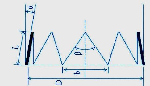
Engel et al proposed to predict acoustic noise of chevron nozzle with RANS-based method, with two nozzle configuration SMC001 and SMC006 initially investigated by Bridges and Brown[14] and numerical data of that configurations proposed by[[37],[38],[39]]. The team also studiedthepotentialofLRTmethodtopredictthefarfield noise by taking thedata fromRANStechniqueasinput. In thisstudy,ahybridtechniquewasutilisedinwhichRANS turbulence model was used to assess sound waves to observeratadistance[35] TheLighthillRayTracing(LRT) approach which Silva et al[40] devised is the noise prediction technique that was employed in this study. By combining the Ray-Tracing theory with source model based on Lighthills acoustic analogy [8], this technique takesintoaccountsoundrefraction.Togetmeanflowdata required for noise prediction,, the approach uses RANS simulation. The LRT approach uses RANS simulation. The LRT has benefit of being computationally inexpensive and suitable for the conceptual design of new nozzle configuration. Considering the finding in this study it is reasonabletosaythatRANSbasedtechniquesrepresenta potent numerical approach for simulating high speed jets[35]
International Research Journal of Engineering and Technology (IRJET) e-ISSN:2395-0056
Volume: 09 Issue: 10 | Oct 2022 www.irjet.net p-ISSN:2395-0072
Fig2 [35]
Burak et al using numerical models and experimentation convergent divergent chevron nozzle’s flow field and farfieldacousticstudieshadbeenconducted.Thiswascarried out for three forward flight Mach values M= 0.1, 0.3 and 0.8.Asecondarynozzlewasemployedintheexperimentto create a confluent flow state in a still environment. The flyingconditionwasarealambient conditioninnumerical forecast. The near nozzle area flow field models and experimental results match up quite well. After 3Dj the numerical predictions begin to diverge from experiment downstream of nozzle exit. This appears to be result of divergent breakdown of vortical structure between the LES and experiment. It is anticipated that the spacing of shock cell constructions would vary since there is gap between the numerical predictions and observations[27] But even when distance between shock cells is increased, the LES is able to accurately forecast the majority of currentflowproperties.Oncomparingchevronandround nozzle, same noise source are present in both cases. The notable difference in chevron is the screech tone is significantlydecreasedandbroadbandshockrelatednoise peaks are moved to slightly higher frequencies with noise reduction of about 3-4dB.Click or tap here to enter text.[28],[38]
DepuruMohanetalinvestigated thenumerical analysisof jet-noise produced by chevron and circular jet. The 4th order space time velocity cross correlation computed using a large eddy simulation flow field, are used to describe the acoustic sources. The axial, radial and azimuthal cross correlations are shown to be reasonably well fitted by Gaussian functions. The ratio of axial to
radial and azimuthal length scales is three to four. “Up to six jet diameter downstream for chevron jet, the cross correlation scales change with azimuthal angle after that they become axisymmetric like these for round jet”[34] “The axial velocity’s fourth order space time cross correlation R1111 is primary source component and R2222, R3333, R1212, R1313 and R2323 cross correlations where 1,2 and 3 stand for axial, radial and azimuthal directions, make significant contributions as well”[34]. When compared to jet which has cross correlations that are generally constant for first 10 jet diameters, the chevron jet exhibits rapid axial distance decline. Within two jet diameter of jet exit the chevron jet amplifies for both R2222 and R3333 cross correlations. A large eddy simulation velocity fields cross correlations. The data and forecasts for far field noise are in very good agreement [41]The chevron nozzle greatly lowers the far fieldnoiseatlowfrequenciesby5-6dBat30°and2-3dBat 90° to jet axis. The chevron nozzles does however marginallyamplifyhighfrequencynoise.Itwasdiscovered that at 30° from jet axis, the R1212 and R1313 cross correlationshavethe biggestcontribution to jet noise and at90°fromthejetaxis whiletheR2323cross correlation haslargestcontribution.RepeatingtheReynoldsaveraged Navier Stokes computations with several turbulence modelsrevealsthatnoiseforecastisessentiallyunaffected byturbulencemodel.[42]
5.1.1Aerodynamics: Turbulence Intensity
I = u’rms / ū (14) Whereū- meanaxialvelocity u’rms -rootmeansquareoffluctuationsaxialvelocity
The breakdownof jet potential coremay be tocausepeak turbulence intensity. The peak turbulence intensity of chevron jet is located three to four jet diameters earlier thatoftheroundjetdueto itsshorterpotentialcore. This shows that the turbulence strength in jet near field is increasedbychevrons.[42]
Streamwise vorticity :( )
x =( / - / ) (15)
Where - mean radial velocity, - mean azimuthal velocity
International Research Journal of Engineering and Technology (IRJET) e-ISSN:2395-0056
Volume: 09 Issue: 10 | Oct 2022 www.irjet.net p-ISSN:2395-0072
Spreading rate(S):
S= ½ / (16)
Where r½ - radial distance at which mean velocity falls tohalfofcentrelinevelocity
The spreading rate increases downstream of tip until it is affected by flow through neighbouring chevron tips. Following that the spreading rate reduces till four jet diameters downstream of chevron tip before gradually changing to linear characteristic. Both the round and chevron jets spread linearly with axial distance with spreadingrateof0.11beyondsixjetdiameterfromnozzle outlet.[42]
5.2 Noise sources:
5.2.1.Cross Correlations:
These correlations have same length and time scales and are shaped like Gaussian Functions. Strong convection in axial direction is the cause of change in peak of cross correlation for axial separation with increasing radial distance the cross correlations rapidly decays. There is a noticeable variance in cross correlations with azimuthal angle because of presence of chevrons creates angular fluctuations in jet flow. Since there is no significant convection in radial and azimuthal direction cross correlationoftheseseparationdon’tpeakshift.
5.2.2.Length Scale: [42]
Length Scales are lowest at chevron roots and highest at chevrontips.
llip/lslant /lroot
This relationshipholdsuptosixjetdiametersfromnozzle exit.
Chevrons significantly diminish the dominating acoustic source (R1111 cross correlations) compared to round jet, by50-60%.DepuruMohan usingRANSandLESidentified themajornoisesourcecorrelations.RANSbasedmodelling approach very well predicts OASPL at high angles to jet axis and reasonably good at low angles to the jet axis. It was found that influence of anisotropy of length scales or farfield noise predictions is roughly3dB. Small variations inproportionalityconstantshave noeffectonforecastsof farfieldnoise.[42]
Uzun 2009 et al conducted numerical simulation studies, the local radial length scale and its eddy turnover frequency are nearly equivalent to local direction length scale and its eddy turnover frequency, at middle of chevron jet mixing layer. This is thought to be a result of greater shear layer mixing brought on axial vorticity generatedbychevron.[30]
Xia et al 2011, conducted numerical simulations for chevron at an isothermal high subsonic flow condition compared with standard method( Ffowcs Williams Hawking(FWH) ) based on LES data and new method RANS simulation method. The high frequency cut-off limit of precise sound prediction is proven to be extended by thenovelacousticapproachwhencomparedtotraditional FWH integral based on LES data. Utilizing experimental datauptofrequenciesashighasSt8andSt6at90degand 30deg respectively. However the low frequency discrepancies are observed to be relatively larger than LES+FWHapproach.[31]
MaxStrouhalnumberwhichgridsupportsiscalculatedby, Stg,max =(2/ ( s/R J))*((1/MJ ) √ /TJ )) (17)
Where, –minimumnumberofgridspacing MJ –JetexitMachnumber
/ TJ ratio of ambient temperature to jet exit temperature
S/RJ relevant grid spacing non-dimensionalised by nozzleexitradius
Nitin et al conducted a studyonhow tousetheimmersed boundary method(IBM) which the authors[44,45] have implemented in a high order finite difference discretization based LES algorithm, to analyse the flow field and noise signature of real world complicated nozzle designs. With fair amount of processing power and use of wall modelling simulations at an experimental scale high Reynolds number may be performed without sacrificing thedownstreamdomain’ssizeorlengthofacousticrecord. The findings of this study show that at least for initial turbulent jet shear layers, the change in far field noise levels brought about by nozzle geometry alterations is comparativelyinsensitivetotheturbulenceinshearlayer. Thisisanoteworthyfindingsinceitimpliesthatturbulent inflow to nozzles need not perfectly match an experimental configuration in order to anticipate the
International Research Journal of Engineering and Technology (IRJET) e-ISSN:2395-0056
Volume: 09 Issue: 10 | Oct 2022 www.irjet.net p-ISSN:2395-0072
geometry alteration on far field noise. This is due to the use of LES/CAA approach to analyse new nozzle design.[43]–[45]
J. Devipriya et al conducted computational studies on chevron nozzle with 1mm wedge thickness and chevron with 2mm wedge thickness.[46]In all subsonic Mach number, it was found that the chevron with 2mm wedge was more effective at reducing possible core length and deforming the jet structure with about 67% of uncontrolledjet[46]
Table 11[46]
Kanmaniraja et al proposed chevrons with sharp, flat, round and U-type edges. The authors felt challenging to select different types of chevrons for parametric experiments since there wasno fixed correlation between chevronshapeandjetnoise.Resultshowthatthechevrons withroundedgeisoptimumdesignfornoisereductionon order of 6dB [47] A simulation of near nozzle area of a moderate Reynolds number cold jet flow exhaust from a chevron nozzle was described by Uzun et.al[27]. Symmetricchevronswith5°penetrationanglewasusedto simulate flow exhaust from a chevron nozzle was used to simulate flow through them. A high order accurate multi block, large eddy simulation algorithm with about 100 million grid points computed both the flow inside the chevronnozzleandfreejetflowoutsideatsametime[48]. Thesimulationaccuratelyshownthenoiseproductionthat results from the higher shear layer mixing caused by chevrons, for first few diameters downstream of nozzle exit. The peak region of spectrum was accurately plotted butpredictioninhighfrequencyregionwaspoor[37]
In order to further investigate complex chevron nozzle flows, Shur et al analysed noise reduction methods like chevron nozzle, bevelled nozzle and dual nozzles. The simulations were run with a goal accuracy of 2-3db for both directing and spectrum with grid size of 2-4 million nodes.Sadanandan et al conducted simulations and
analysis at stagnation temperature 286.44K and pressure=178200Pa.A sinusoidal M-lobed chevron nozzle produces1.6 decibel less noisethana baseline nozzle and 0.93dB less noise than a chevron symmetric nozzle. This study shows that it had no impact on performance of nozzle.
Rajashreeetaladdedcorrugatedplatesnexttoconvergent nozzle’s exit which also contains chevrons at its trailing edge. The angle of corrugated plates is adjusted after evaluating nozzle settings in order to reduce noise emissionwithminimalthrustloss.Accordingtothisstudy, usinganozzlewithcorrugatedplateat115°reducesnoise. When compared to other four types of nozzle the corrugated plate nozzle at 115° increases the mixing rate of fluid flow from output of nozzle with ambient air[49].Pranav M et al conducted studies on five nozzle configuration and found M-shaped lobe with sinusoidal curve is most efficient in noise reduction[50]M shaped sinusoidal lobe produce nearly 20db less than baseline nozzle.[50]
Table 12[50]
[51]–[57]
2022, IRJET | Impact Factor value: 7.529 | ISO 9001:2008 Certified Journal | Page409
International Research Journal of Engineering and Technology (IRJET) e-ISSN:2395-0056
Volume: 09 Issue: 10 | Oct 2022 www.irjet.net p-ISSN:2395-0072
Table 13 [51]
Irfan nazir et al[9] conducted acoustic analysis on N8 chevronnozzlewithvaryingthetipangleinrangeof20 to 110 . It is clear from acoustic analysis of chevron nozzle thatastipangleincreases,acousticpowerleveldecreases. Although N8-108 model exhibits strongest noise suppression and has only 100.45dB acoustic power, it should be noted that this sound is detected at a larger surface area than that of other models, leading to more pressure taking into account all relevant variables It is determined that efficient model in the N8 configuration eitherbeN8β88.8orN8β101.6
Table 14 [9]
Boundary conditions:Temperature=300K,Inlet Pressure=170023.34Pa,OutletPressure=28441.92Pa
Various Noise reduction methodologies of Jet engine are under research. Chevron nozzle was one among such methodologieswhichfoundtobeimpressivewithitsnoise reduction capabilities. Even though it is promising still it affectsthe overall thrustperformance ofengine.So recent research are focussed towards reducing noise without affecting the engine performance. Researcher’s findings suggest that performance of chevron nozzles is not determinedbypenetration,lengthornumberofchevrons. Howeverthechevronnozzle’saeroacousticsperformance isdeterminedbynetstrengthofthestreamwisevorticesit generates.Thereforeitappearsthatathoroughknowledge of the altered flow field and nearby acoustic field that are responsible for noise reduction caused bychevrons under subsonic conditions is still lacking, and further systematic investigations are needed to understand the underlying processes.
The bulging of shear layer closer to nozzle exit is exacerbated by early penetration into weaker mixing layer. Stronger streamwise vortices that produce quick mixingandhighercentrelinevelocitydecayareindications ofenhancedshearlayer bulging.Thelocationofdominant noisesourcedeterminedacousticmeasurementoflocation of maximum decay rate of centreline velocity by time decay technique. Depending on their design chevrons are found to efficiently move the noise source towards the nozzle exit. Therefore dominating noise directed towards lowerpolaranglesinthedistantfieldcanbeminimisedat price of increasing level towards higher polar angles by moving noise source closer the nozzle exit. Chevron may reduce the hydrodynamic component of near field pressure at region of dominating noise, according to a decomposition of hydrodynamic and acoustic pressure in near field using decay law. Notched nozzle along with chevronsarealsofoundtoexcellentin noisereduction.In earlierdesignandresearchitisfoundthatchevronnozzle found to reduce noise to a max of 3-5dB.Along with chevron and notched nozzle studies reveal that bypass engine water or nitrogen injection techniques also substantiallyreducejetnoiseupto6dB.
International Research Journal of Engineering and Technology (IRJET) e-ISSN:2395-0056
Volume: 09 Issue: 10 | Oct 2022 www.irjet.net p-ISSN:2395-0072
[1] Parth Parmar, Darshil Trivedi, Kishan Randhesiya, and Ravi Shingala, “Modeling and Analysis of Different Chevron Nozzle for Noise Reduction,” International Journal ofEngineeringresearchandTechnology, vol. 10, no. 1, 2021, doi: 10.17577/IJERTV10IS010263.
[2] Sasi Kumar M, Abirami K, Sandhiya k, Vijay G, and Vishnu Varthan S, “NOISE REDUCTION ANDTHRUST ENHANCEMENT IN VARIOUS MODIFIED CHEVRON NOZZLE,” Int J Dev Res, vol. 8, no. 1, pp. 18540–18544, 2018, Accessed: Oct. 04, 2022. [Online]. Available: https://www.journalijdr.com/noisereduction-and-thrust-enhancementvarious-modified-chevron-nozzle
[3] D. Casalino, F. Diozzi, R. Sannino, and A. Paonessa, “Aircraft noise reduction technologies: A bibliographic review,” Aerosp Sci Technol, vol. 12, no. 1, pp. 1–17, Jan.2008,doi:10.1016/j.ast.2007.10.004.
[4] A. R. Pilon, R. W. Powers, D. K. McLaughlin, and P. J. Morris, “Design and analysis of a supersonic jet noise reduction concept,” J Aircr, vol. 54, no. 5, pp. 1705–1717, Sep. 2017,doi:10.2514/1.C033977.
[5] JamesLighthill,“James-Lighthill,” wikipedia
[6] “Aircraft Engines and Gas Turbines,” Internet.
[7] P.S.TideandK.Srinivasan,“Novelchevron nozzle concepts for jet noise reduction,” Proc Inst Mech Eng G J Aerosp Eng, vol. 223, no. 1, pp. 51–67, Feb. 2009, doi: 10.1243/09544100JAERO347.
[8] J.Lighthill,“Onsoundgeneratedaerodynam ically ,I.General theory By M. J.Lighthill,” Royal Society , 1951, doi: https://doi.org/10.1098/rspa.1952.0060.
[9] I. N. Wani, S. Chaitanya, D. Singh Sisodiya, and A. Kulshreshtha, “Design And Acoustic AnalysisOfN8ChevronNozzleWithVaried Tip Angle(β),” IOSR Journal of Mechanical
and Civil Engineering (IOSR-JMCE) e-ISSN, vol. 19, no. 2, pp. 35–38, 2022, doi: 10.9790/1684-1902013538.
[10] Kumar Akshay and Radhakrishnan Arjun, “Noise Reduction in Jet Engine using Chevron Nozzle,” International Research Journal of Engineering and Technology, 2018, Accessed: Oct. 04, 2022. [Online]. Available: https://www.irjet.net/archives/V5/i5/IRJE T-V5I5613.pdf
[11] J. H. Mabe, F. T. Calkins, and M. B. Alkislar, “Variable area jet nozzle using shape memory alloy actuators in an antagonistic design,” in Industrial and Commercial Applications of Smart Structures Technologies 2008, Mar. 2008, vol. 6930, p. 69300T.doi:10.1117/12.776816.
[12] D. Reed, W. Herkes, and B. Shivashankara, “THE BOEING QUIET TECHNOLOGY DEMONSTRATOR PROGRAM,” 2006. Accessed:Oct.04,2022.[Online].Available: https://www.icas.org/ICAS_ARCHIVE/ICAS 2006/PAPERS/745.PDF
[13] N. H. Saiyed, K. L. Mikkelsen, and J. E. Bridges, “Acoustics and thrust of quiet separate-flow high-bypass-ratio nozzles,” AIAA Journal, vol. 41, no. 3, pp. 372–378, 2003,doi:10.2514/2.1986.
[14] J. Bridges and C. A. Brown, “Parametric Testing of Chevrons on Single Flow Hot Jets,” 2004. doi: https://doi.org/10.2514/6.2004-2824.
[15] K. B. M. Q. Zaman, J. E. Bridges, and D. L. Huff, “Evolution from ‘tabs’ to ‘chevron technology’ - A review,” International JournalofAeroacoustics,vol.10,no.5–6.pp. 685–710,Oct.01,2011.doi:10.1260/1475472X.10.5-6.685.
[16] B. Callender, E. Gutmark, and S. Martens, “Near-field investigation of chevron nozzle mechanisms,” in AIAA Journal, Jan. 2008, vol. 46, no. 1, pp. 36–45. doi: 10.2514/1.17720.
International Research Journal of Engineering and Technology (IRJET) e-ISSN:2395-0056
Volume: 09 Issue: 10 | Oct 2022 www.irjet.net p-ISSN:2395-0072
[17] J.HilemanandM.Samimy,“Effectsofvortex generating tabs on noise sources in an ideally expanded mach 1.3 jet,” Sage Journals, pp. 35–63, 2003, doi: https://doi.org/10.1260/14754720332243 6935.
[18] P. S. Tide and K. Srinivasan, “Effect of chevron count and penetration on the acousticcharacteristicsofchevronnozzles,” ELSEVIER, Applied Acoustics, vol. 71, no. 3, pp. 201–220, Mar. 2010, doi: 10.1016/j.apacoust.2009.08.010.
[19] R. H. Schlinker, J. C. Simonich, D. W. Shannon, R. A. Reba, and F. Ladeinde, “Supersonic Jet Noise from Round and Chevron Nozzles: Experimental Studies,” 2009.doi:https://doi.org/10.2514/6.20093257.
[20] O. Rask, J. Kastner, and E. Gutmark, “Understandinghowchevronsmodifynoise inasupersonicjet withflighteffects,” AIAA Journal, vol. 49, no. 8, pp. 1569–1576, Aug. 2011,doi:10.2514/1.J050628.
[21] J.Y.HeandY.B.Xu,“ExperimentalAnalysis for Jet Noise Reduction of Chevron PylonBased Nozzles,” Adv Mat Res, vol. 1078, pp. 183–186, Dec. 2014, doi: 10.4028/www.scientific.net/amr.1078.183.
[22] P. Kaleeswaran and P. Shanmughasundaram, “Experimental and statistical analysis on the noise reduction usingchevronnozzleinsupersonicfreejet,” U.P.B.Sci.Bull.,SeriesD, vol. 78, no. 3, 2016, Accessed:Oct.04,2022.[Online].Available: https://www.scientificbulletin.upb.ro/rev_ docs_arhiva/full5ff_208250.pdf
[23] L. P. Bastos, C. J. Deschamps, and A. R. da Silva,“Experimentalinvestigationofthefarfield noise due to jet-surface interaction combined with a chevron nozzle,” ELSEVIER,Applied Acoustics, vol. 127, pp. 240–249, Dec. 2017, doi: 10.1016/j.apacoust.2017.06.008.
[24] S. R. Nikam and S. D. Sharma, “Effect of chevron nozzle penetration on aeroacoustic characteristics of jet at M = 0.8,”
Fluid Dyn Res, vol. 49, no. 6, Oct. 2017, doi: 10.1088/1873-7005/aa8501.
[25] B. C. Heberling, “Numerical Investigationof a Shielded Chevron Nozzle,” Aerospace Research Central (ARC)-AIAA, 2019, doi: https://doi.org/10.2514/6.2019-0254.
[26] G. Cican, M. Deaconu, and D. E. Crunteanu, “Impact of using chevrons nozzle on the acoustics and performances of a micro turbojet engine,” Applied Sciences (Switzerland),vol.11,no.11,Jun.2021,doi: 10.3390/app11115158.
[27] A. Uzun and M. Yousuff Hussaini, “Noise Generation in the Near-Nozzle Region of a Chevron Nozzle Jet Flow,” 2007. doi: https://doi.org/10.2514/6.2007-3596.
[28] Markus O. Burak, Lars-Erik Eriksson, David Munday,EphrainGutmark,andErikPrissel, “ExperimentalandNumericalINvestigation ofa SupersonicC-DChevronNozzle,”2009. doi:https://doi.org/10.2514/6.2009-4004.
[29] M.L.Shur,P.R.Spalart,M.K.Strelets,andA. vGarbaruk,“Analysisofjet-noise-reduction concepts by large-eddy simulation,” Sage Journals, vol. 6, no. 3, pp. 243–285, 2007, doi: https://doi.org/10.1260/14754720778241
[30] A. Uzun and M. Ramasamy, “Simulation of noise generation in near-nozzle region of a chevron nozzle jet,” AIAA Journal, vol. 47, no. 8, pp. 1793–1810, Aug. 2009, doi: 10.2514/1.36659.
[31] H. Xia etal.,“HybridRANS-LES Modeling of Chevron Nozzles with Prediction of Far Field Sound,” 2011. doi: https://doi.org/10.2514/6.2011-21.
[32] V. Vlasenko, S. Bosniakov, S. Mikhailov, A. Morozov, and A. Troshin, “Computational approach for investigation of thrust and acoustic performances of present-day nozzles,” ProgressinAerospaceSciences,vol. 46, no. 4. pp. 141–197, May 2010. doi: 10.1016/j.paerosci.2009.10.002.
International Research Journal of Engineering and Technology (IRJET) e-ISSN:2395-0056
Volume: 09 Issue: 10 | Oct 2022 www.irjet.net p-ISSN:2395-0072
[33] S.F.Birch,D.A.Lyubimov,V.P.Maslov,and A. N. Secundov, “Noise Prediction for Chevron Nozzle Flows,” 2006. doi: https://doi.org/10.2514/6.2006-2600.
[34] S. Karabasov, C. Bogey, and T. Hynes, “An investigation of the mechanisms of sound generation ininitiallylaminarsubsonicjets using the Goldstein acoustic analogy,” J Fluid Mech, vol. 714, pp. 24–57, Jan. 2013, doi:10.1017/jfm.2012.448.
[35] R.C.Engel,C.R.I.Silva,andC.J.Deschamps, “Application of RANS-based method to predict acoustic noise of chevron nozzles,” AppliedAcoustics,vol.79,pp.153–163,May 2014,doi:10.1016/j.apacoust.2013.12.019.
[36] B. S. Aflalo, S. José dos Campos, S. PauloBrazil Odenir de Almeida, and J. Barbosa, “CFD and CAA Analysis of Single Stream Isothermal Jets with Noise Suppression Devices,” 2010. doi: https://doi.org/10.2514/6.2010-4020.
[37] S. F. Birch, D. A. Lyubimov, V. P. Maslov, A. N. Secundov, and K. Ya Yakubovsky, “A RANS based Jet Noise Prediction Procedure,” 2007. doi: https://doi.org/10.2514/6.2007-3727.
[38] H. Xia, P. G. Tucker, and S. Eastwood, “Large-eddy simulations of chevron jet flows with noise predictions,” Int J Heat Fluid Flow, vol. 30, no. 6, pp. 1067–1079, Dec. 2009, doi: 10.1016/j.ijheatfluidflow.2009.05.002.
[39] J. Bin, A. Uzun, and M. Yousuff Hussaini, “Adaptive mesh refinement for chevron nozzlejetflows,” ComputFluids, vol.39, no. 6, pp. 979–993, Jun. 2010, doi: 10.1016/j.compfluid.2010.01.008.
[40] C.R.I.daSilva,J.R.Meneghini,M.Azarpeyv, andR.H.Self,“Refractioneffectsonfar-field noise predictions and sources distribution of coplanar coaxial jet flows,” 2011. doi: 10.2514/6.2011-2749.
[41] Roberto Ilário Silva and Carlos DA, “Development of a novel RANS- based method for the computational
aeroacousticsofhighspeedjets,”University ofSaoPaulo,Brazil,2011.Accessed:Oct.04, 2022. [Online]. Available: https://scholar.google.com/scholar?hl=en& as_sdt=0%2C5&q=Development+of+a+nov el+RANS+based+method+for+the+computational+a eroacoustics+of+&btnG=
[42] N. K. D. Mohan etal., “Acousticsourcesand far-field noise of chevron and round jets,” AIAAJournal, vol. 53, no. 9, pp. 2421–2436, 2015,doi:10.2514/1.J052973.
[43] N. S. Dhamankar, G. A. Blaisdell, and A. S. Lyrintzis,“Analysisofturbulentjetflowand associated noise with round and Chevron NozzlesusinglargeEddysimulation,”2016. doi:10.2514/6.2016-3045.
[44] N. Dhamankar and V. Kolobov, “Implementation of a Sharp Immersed Boundary Method in a 3-D Multi-block LargeEddySimulationToolforJetAeroa..,” tics and Astronautics, 2015, doi: https://doi.org/10.2514/6.2015-0504.
[45] N. S. Dhamankar, G. A. Blaisdell, and A. S. Lyrintzis, “Implementation of a wallmodeledsharpimmersedboundarymethod in a high-order large eddy simulation tool for jet aeroacoustics,” in 54th AIAA Aerospace Sciences Meeting, 2016, vol. 0. doi:10.2514/6.2016-0257.
[46] J. Devipriya and Kanimozhi, “Numerical investigation of mixing characterstics of chevron nozzle by passive controls method,” in IOPConferenceSeries:Materials Science andEngineering, 2017, vol. 197, no. 1. doi: 10.1088/1757899X/197/1/012082.
[47] Kanmaniraja, R. Freshipali, J. Abdullah, K. Niranjan, K. Balasubramani, and v. R. Sanal Kumar, “3D Numerical Studies on Jets AcousticCharacteristicsofChevronNozzles for Aerospace Applications,” International Journal of Aerospace and Mechanical Engineering, vol. 8, no. 9, 2014, Accessed: Oct. 04, 2022. [Online]. Available: https://citeseerx.ist.psu.edu/viewdoc/dow
International Research Journal of Engineering and Technology (IRJET) e-ISSN:2395-0056
Volume: 09 Issue: 10 | Oct 2022 www.irjet.net p-ISSN:2395-0072
nload?doi=10.1.1.651.6415&rep=rep1&typ e=pdf
[48] MojtabaSadeghianandMofidGorjiBandpy, “TechnologiesforAircraft NoiseReduction: A Review,” Journal Of Aeronautics and Aerospace Engineering, 2020, doi: 10.35248/2168.
[49] Rajashree V, Antony D T, Palanisamy R, Prakash S, and Ranjith Kumar R, “Design and Analysis of a Nozzle to Enhance Noise Suppression,” 2018. Accessed: Oct. 04, 2022. [Online]. Available: https://www.ijarnd.com/manuscript/desig n-and-analysis-of-a-nozzle-to-enhancenoise-suppression/
[50] M. Pranav and Ravikumar P, “Numerical InvestigationofLobeDesigninModification inChevronNozzleforNoiseReduction,” Int JResApplSciEngTechnol, vol. 8, no. 4, Apr. 2020, Accessed: Oct. 04, 2022. [Online]. Available: https://www.semanticscholar.org/paper/N umerical-Investigation-of-Lobe-Design-inin-NozzlePranav/592e041c5c6677c5df3ef7c03bcf57 2100a0fabe
[51] T. M. Raef, A. Elzahaby, S. Abdallah, M. K. Khalil, and S. Wagdy, “Experimental and Numerical Investigations of Noise from Micro Turbojet Engine,” Int J Sci Eng Res, 2015, Accessed: Oct. 04, 2022. [Online]. Available: https://www.researchgate.net/profile/Ta merRaef/publication/281345025_Experimenta l_and_Numerical_Investigations_of_Noise_fr om_Micro_Turbojet_Engine/links/55e2d5d 608ae2fac471f9ab7/Experimental-andNumerical-Investigations-of-Noise-fromMicro-Turbojet-Engine.pdf
[52] M.Balara,A.Balara,andD. Matisková,“The Design and the Properties of a Jet Engine with the Rear Bypass of the Air,” TEM Journal, vol. 9, no. 4, pp. 1791–1799, Nov. 2020,doi:10.18421/TEM94-62.
[53] P. S. Tide and V. Babu, “Numerical predictions of noise due to subsonic jets
from nozzles with and without chevrons,” Applied Acoustics, vol. 70, no. 2, pp. 321–332, Feb. 2009, doi: 10.1016/j.apacoust.2008.03.006.
[54] MichelUlf,“Thebenefitsofvariableareafan nozzles on turbofan engines,” Aerospace Research Central(ARC)-AIAA, 2011, doi: https://doi.org/10.2514/6.2011-226.
[55] C. K. W. Tam, K. Viswanathan, K. K. Ahuja, and J. Panda, “The sources of jet noise: Experimental evidence,” J Fluid Mech, vol. 615, pp. 253–292, 2008, doi: 10.1017/S0022112008003704.
[56] K. B. M. Q. Zaman~, “FLOW FIELD AND NEAR AND FAR SOUND FIELD OF A SUBSONIC JET,” 1986. doi: https://doi.org/10.1016/S0022460X(86)80170-5.
[57] A.V.G.Cavalieri,P.Jordan, T.Colonius,and Y. Gervais, “Axisymmetric superdirectivity in subsonic jets,” J Fluid Mech, vol. 704, pp. 388–420, Aug. 2012, doi: 10.1017/jfm.2012.247.
2022, IRJET | Impact Factor value: 7.529 | ISO 9001:2008 Certified Journal | Page414